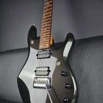
Couldn't leave well enough alone: A tale of modding a 2020 Luke
Outside
I didn’t quite dig the hardware colour (the chrome plastic looks cheap IMHO), so I switched the tremolo arm, switch tip, knobs, and tuner buttons as a little nod to the 25th Anniversary Luke. I also tried chrome single coil covers, but it looked weird.

I also put on Wilkinson locking saddles. I switched out the black screws/springs to chrome. Partly for aesthetics, but also because I needed really short height screws due to how I set up the bridge. The black lock screws have a special plating, so they had to stay. Clear plastic tubing went inside the tremolo springs to stop ringing.


Inside
Oh, where to begin? All the electronics are PCB-mounted. Even the tone cap is an SMD component! Which I had the great honour of having to change, since I prefer 0.010 uf over 0.022 uf.
I also had to build my own DPDT+SPST push/push pot to use as a tone pot. Yep, you heard that right. This took many tries, and resulted in a lot of discarded switches and parts. One wrong move, and the whole thing is useless. I could write pages about just this “creation”, and all the work that went into finding all the right parts, and then Frankenstein-ing™ them together through trail and error. Basically, drill a hole in the DPTP housing, glue little wings made of metal can lids on a micro switch, then glue that to the DPDT housing.


WHY did I torture myself with this? Well, the guitar has a pickup level compensation feature, which is used to compensate (boost) the output level of the single coils to match the humbucker. Or in the case of this particular abomination, I use the DPDT to switch the humbucker between series/parallel, and the SPST micro switch activates the pickup comp, so I don’t get any volume drop when running the bucker in parallel.


Which lead me onto the next thing: The Luke has non adjustable pickup heights. So how do they control the relative levels of pickups when using the pickup comp? Like if one position on the 5-way needs less boost? With board mounted SMD resistors! Yay… But, I wanted more control, so I used trim pots. The white trimpot controls pos 1-3, the blue pos 4. The stock PU comp trimpot on the PCB board controls the humbucker when in parallel, AND both of the other trimpots. That’s because they’re in series with the main trimpot, but in parallel with each other and the micro switch.

And the heart of this disaster: The custom made 8 pole stacked M switch from Eyb! Why this particular switch? Because this is the ONLY switch that can make all this work. I need all 8 poles + an extra long lever. Basically, this is the number of poles that are assigned to each purpose:
2: Pickup selection (hot)
2: Ground (one for load resistor, other for splitting/grounding)
2: Bridge pickup series/parallel & splitting
1: Pickup comp (trim pots, micro switch on tone pot)
1: Selects if the middle pup is grounded normally, or goes to the silent circuit (noise cancelling system).


So what does all this give me that’s different than the stock wiring?
Pos 1-3 are basically the same. Standard strat neck, neck & middle, middle. Silent circuit connected, so there’s less noise. The only difference is that I have the extra trimpot to fine tune the output level.
Pos 4 is quite different though. Stock, it’s middle (+ silent circuit) & humbucker (internal series). Now, the bridge is split to the screw coil, and the middle is grounded normally (no silent circuit). It’s done like this to achieve noise cancellation. This position is quite loud, so it needed its very own trimpot to tame it.
Pos 5 is where the push/push “freak of a pot” comes in. If the push/push is down, it’s like stock: Full series humbucker. When it’s up, the humbucker is wired in parallel, and the pickup compensation is engaged.
Was it worth it? Yes.
Would I have done it if I knew what a massive task it would be? No way. Maybe. Yes.
If anyone has questions about any particular part, I’ll answer them to the best of my masochistic ability.
Source: http://forums.ernieball.com


