DIY Workshop: Goldtop Conversion Part Three
After a few months on the back burner, Huw Price cracks on with his Greco conversion project, and with a little help from his friends, he takes some big steps towards his dream mid-50s Goldtop replica…
In the last instalment of this Goldtop conversion series, I signed off by saying how I marked the bridge position on the body, but would hold off drilling the bushing holes until after the pickup holes were plugged. Shortly afterwards, I was asked to convert a Les Paul 50s Tribute to a wrapover bridge and it gave me pause for thought.
As usual, I found a very helpful online video on bridge placement where the guitar builder strung up the LP-style guitar he was building with the wrapover bridge shimmed up on blocks of wood. The strings have to be secured and there are two ways to do it.
If it’s a scratch build, you can fix the tailpiece using a single screw in the rear strap button’s eventual location. If it’s a tune-o-matic to wrapover conversion, you can actually use the existing stoptail. For this project, I’ve decided to use a tailpiece because the original Greco bridge and tailpiece were fitted off-centre. I manage to track one down online for just a fiver, and we’re ready to go.
The idea is to string the guitar up, tune it to pitch and slide the bridge to find the position where the strings all intonate as closely as possible. You also need to ensure that the strings pass directly over the holes in the wrapover bridge, and the holes in question are those at the back of the bridge from where the strings emerge rather than the front holes. Lastly, the bride has to be centred so the spaces between the E strings and the outer edges of the fingerboard are equal.
Once you’re convinced you have found the optimum position, take a brad-point drill bit with a diameter equal to the width of the post openings. Set the bridge’s ‘fine tune’ grub screws so each protrudes about 3mm into the opening and position the brad bit inside the openings with the point against the guitar’s top and the side against the grub screw. Try to ensure it’s perfectly upright and lightly tap the top to mark the body. You’re now ready to drill the post holes.
If the bridge is square to the body you can use the original tailpiece to align the wrapover
Bolt Action
Before drilling holes for the post bushings, decisions have to be made about which bushings to use. The original studs can’t be recycled because they don’t provide a slot to retain the bridge. Instead their purpose is to hold a tailpiece flat to the body or clamp it using spacers.
When you start shopping around, it soon becomes apparent that there are various options in an equal number of diameters and lengths. Adding to the complication is that some are imperial while others are metric. It seems that even vintage and modern Gibson hardware varies somewhat.
Imperial bushings should measure half an inch in diameter, but length varies from 7/8 to one inch.
This guitar’s original bridge was off centre so a trapeze tailpiece helps to align the wrapover
It seems that earlier Goldtops and Juniors also had shorter bushings and in some cases, they have begun to lean forward due to string pull. Gibson must have become aware of this issue quite quickly, because bushing length was increased and the bridge pickup rout was moved 1/8-inch closer to the neck to keep a bit more wood between the bushing and pickup holes on the problematic treble side.
Having been impressed with the Mojo Axe compensated bridge kit I installed on the 50s Tribute, I decide on Mojo Axe’s relic’d 1.19-inch bushings with the accompanying one-inch long studs. My feeling is that the longer bushings will be more securely anchored in the body and that the extra depthis more likely to facilitate tone transfer.
The left stud is unsuitable for a wrapover and the Gotoh on the right is shorter than the Mojo Axe parts we are using
Deep & Wide
Before drilling any new holes in the guitar, there are four old ones to plug. The bridge post holes are easy enough because the holes were 6mm in diameter and Axminster Tools & Machinery keeps a nice selection of beechwood dowelling in stock. The Greco bushing holes are problematic because they are 11mm in diameter and I can only find 10mm and 12mm.
Widening the hole with a 12mm drill bit creates some chip out around the opening, but with the plug glued in with Titebond Original and a bit of two-pack filler, the results aren’t too bad. Suitably chastened, I decide to take no chances with the new bushing holes. Sometimes you really do need to use professional tools, so I accept my mate Mike Phillips’ offer to use his pillar drill for the new bushing holes.
Tapering the ends of the dowels makes it easier to get them started in the holes
It’s often hard to find specialist tools in imperial sizes, unless you order from America and swallow the cost. Since the Mojo Axe bushings require a half-inch bushing hole, I decide a 13mm brad point bit from Axminster will probably be okay. It’s a beast of a thing and I certainly wouldn’t want to use it in a hand drill.
With the pillar drill’s platform adjusted square to the bit, I carefully lower the bit and adjust the body until the position marks I made are directly under the tip. With the drill switched on, I slowly lower the bit until it just begins to cut into the body, then lift it and lower it again.
This bushing plug has been glued with Titebond and needs levelling
The trick is not to try and drill the hole all in one go. Clearly you need to ensure that the body doesn’t move, but by drilling, lifting slightly, blowing away the wood shavings and drilling some more, you can achieve very clean and accurate results with no chippings or drill burn.
With a bit of filler, this levelled post plug looks okay
Pulling The Plugs
It’s probably a lot easier to turn a P-90 rout into a humbucker rout, but there’s no going back now. However, I have never been under any illusions that my woodworking abilities are up to making routing templates and wood plugs that will be a tight enough fit.
Fortunately, Jim Lewis of Lewis & Lockyer in Bedwas offered to help. In addition to owning a CNC router, Jim is a guitar enthusiast and TGM reader, so having carefully measured up, he made me routing templates for the plugs and P-90 holes, plus a selection of maple and mahogany plugs cut to fit.
The body is placed on the pillar drill and masking tape marks the depth stop on the 13mm brad point drill bit
For the plug routes, I need to build a cradle to hold the guitar steady and position the routing template. After a rummage about in the shed, I go with a plywood base and a couple of sides glued and screwed on top. The sides are placed to wedge the lower bout and with the body centred, I glue two further wood strips across the waist that are just slightly lower than the body in height.
The body pushes in from the back and centres itself against the sides and the struts. Next, I cut hardwood strips in lengths of roughly 7cm and screw them onto the two struts. With protective pieces of cork between the hardwood strips and the body, the strips effectively ‘clamp’ the body against the base when the screws are tightened.
Care is taken to align the drill bit with the marked position holes
The router template isn’t sufficiently wide to bridge the cradle width, so I secure it onto a wider piece of MDF using double-sided tape and four screws, and rout an opening in the MDF to match the plug template. The MDF is placed across the cradle, lined up over the bridge pickup rout and clamped in position.
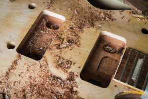
Using a bearing-guided router bit, I begin by opening up the edges in passes, with depth increasing by about 5mm each time. This continues until I’ve skimmed the bottom of the rout to remove the last bit of finish and expose the wood for gluing.
The second bushing hole is drilled and both turn out very cleanly
I follow the same procedure for the neck pickup but it doesn’t go quite as well. My router is fairly rudimentary and I use quarter-inch shank bits. Once things go beyond a certain depth, the bits tend to chatter about and the cut is never as clean as I’d like. Still, the result isn’t too bad and since the plan is to veneer the top, the filled gaps shouldn’t be an issue.
These routing templates and plugs were very kindly supplied by TGM reader Jim Lewis
Block Party
By sheer coincidence, the depth of the bridge pickup cavity ends up being just about perfect for the one of the maple bridge pickup plugs. So that one simply needs to be glued and clamped up. In contrast, the neck pickup plug has to be modified to provide channels for the pickup and switch wires.
Unlike Gibson, Greco didn’t rout wiring channels into the mahogany part of the body before gluing the maple cap. Instead they drilled holes from the corner of the neck pickup rout into the switch hole and – presumably before the neck was attached – diagonally from the neck pocket through to the control cavity.
A simple routing cradle to hold the body is made from scraps of wood
Rather than stack a maple plug on top of a mahogany plug, I decide to use one of the deep mahogany plugs Jim provided, notching it out on the bass side so the switch wire hole will be exposed once the P-90 hole is routed to the right depth. I place it in the hole and draw around the top edge to determine how much material will have to be removed to bring the plug flush. Before installation, I pre-carve the plug’s top surface using a small block plane. It’s offered up to the body several times and I eventually call it quits with about 1mm proud of the body.
The bridge pickup hole is enlarged ready for plugging
Various glues would be suitable, but I decide on Cascamite. It’s the same type of glue that Gibson used for fixing maple caps on Les Pauls, so it’s worth noting they didn’t use hide glue everywhere during the 1950s. Cascamite is incredibly strong and has good gap filling properties – which is just as well.
You do need to mix the powder with water to make the glue, but it’s easy enough if you follow the instructions – two parts Cascamite to one part water by weight. The glue is applied by brush and the plugs are clamped in position. Cascamite has a one-hour open time, but it needs about six hours to go off completely and the clamps don’t need to be set too tight.
Both holes are now ready for plugs and the humbucker ‘ear’ holes will eventually be hidden
The final part of the plug saga turns out to be a lot more enjoyable than anticipated. I fix some 220-grit paper onto the base of a flat sanding block and surround the plugs with masking tape to protect the body. Before long, the plugs are sanded level with the masking tape, which is then removed and the sanding continues until the blocks are level with the body. There are some small gaps in places around the plugs, but this is easily dealt with using two-pack wood filler and a bit more sanding.
Two In The Bush
Now with a solid block of maple glued in place, I feel confident enough to install the stud bushings. However, there’s the ground wire to consider. The original ground wire was routed through to the stop tailpiece bushing, but with that removed, we’ll have to connect it to the new bridge bushing.
With a generous application of Cascamite glue, the plugs are clamped and left for six hours
For this I use a 10cm long drill bit and start with the tip a few millimetres below the top of the bushing hole with the bit at a shallow angle. The opposite edge of the hole is protected with a few strips of masking tape. Having calculated where Greco drilled the wire channel, I take aim, and strike lucky. A bare ground wire is threaded through to the control cavity and folded down against one side of the bushing hole. I screw one stud half way into the bushing, line the bushing up over the hole and gently tap it into the body using a mallet.
A 10cm bit is used to make a ground wire channel between the treble side bushing hole and Greco’s drilled wire channel
This wedges the wire between the bushing and the body and it’s held tightly in place. I quickly install the second bushing and string up the guitar.
With only end to end adjustment, setting the action is easy and a few turns on the grub screws brings the intonation under control. Now if I squint and try very hard, I can begin to see a Goldtop emerging at the end of a very long tunnel.
Special thanks to Jim Lewis & Mike Phillips for their help with this stage of the conversion.The post DIY Workshop: Goldtop Conversion Part Three appeared first on The Guitar Magazine.
Source: www.guitar-bass.net


